Section: 13
Hours: 2
Today I double checked my work and reread the construction manual in preparation for joining the leading edge pieces to the spar. When I trial fitted the outboard leading edge assemblies, I noticed I had overlooked breaking the joining edges. Since the holes were already dimpled, I couldn't use my edge break roller. I manually used my duck bills and put a slight break along all the edges.
In looking over the rivet call outs, I saw the note about holes for the tie down lugs. I got out the step drill and enlarged the already drilled tie down holes to 3/8".
Next I noticed there were some empty holes in the spar. On further investigation I realized I had overlooked some nut plates that were called out back in chapter 13. They are all the way out at the end of the spar and were off to the side of one of the manual drawings. I counter sank the holes and riveted in the nut plates. It was a little more work moving the spar around now that the ribs, sub spar and top skins are attached.
Section: 16
Hours: 2.5
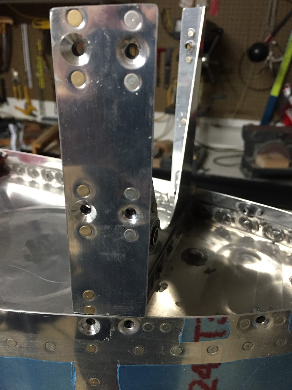
I felt pretty confident that the outboard leading edge assemblies were ready for attaching so I moved on to finishing up the tanks. I counter sank the holes at the inboard side of the tanks using the #8 counter sink and finishing up with the #30 because the #8 would not go all the way to the final depth.
I hadn't done the pressure test yet to check for leaks, so I rounded up all the plugs, drains, strainers, fuel caps, balloons, air valve, thread sealant and a bicycle pump and went at it.
You have to insert plugs in the remaining open holes. I spent some time researching the proper torque values and what sealant to use. After perusing chapter 5 and reading several threads on Van's Airfare it looks like you apply thread sealant and then finger tighten the plugs. Then you tighten another 1.5 to 2 revolutions with the wrench. Same thing for the fuel strainer and the fuel drain plug. Here's the sealant that I bought at the local auto parts store.
I found the gas cap was a little loose, so I tightened the nut on the inside of the cap until I felt a little more force on the locking arm when closing it up. Then I taped over the gas cap with clear packing tape to fully seal it.
Here I've pumped air into the tank just enough to inflate the balloon that is tied to the vent line. The balloon stays inflated for about an hour and then slowly deflates, so I have a leak somewhere. Tomorrow I'll get out the soapy water and spray the tank down to look for leaks. Right now I suspect the balloon is leaking, but the soap will tell.
Disclaimer: This blog is to provide others insight into my experience and for my own historical purposes. Airplane construction is a serious affair. I have no authoritative skills relating to airplane construction. As such, any use of the information contained on this blog is at your own risk.
Showing posts with label Section 16. Show all posts
Monday, May 9, 2016
Sunday, May 8, 2016
Section: 16
Hours: 2
Today is Mother's day so I didn't do much in the garage. I did finish up the last couple tasks for section 16.
I riveted the outboard aileron bracket which ties in the end rib to the subpar.
Then I did the counter sinks for the nut plates at the inboard end of the top wing skins. These are large countersinks to fit a skin dimpled for a #8 screw. The #8 countersink would not go in far enough- the pilot pin gets stopped by the nut plates since they taper and the pilot doesn't. I cleared out all the holes with the #8 as deep as it would go and then carefully finished with the #30 countersink to full depth.
Hours: 2
Today is Mother's day so I didn't do much in the garage. I did finish up the last couple tasks for section 16.
I riveted the outboard aileron bracket which ties in the end rib to the subpar.
Then I did the counter sinks for the nut plates at the inboard end of the top wing skins. These are large countersinks to fit a skin dimpled for a #8 screw. The #8 countersink would not go in far enough- the pilot pin gets stopped by the nut plates since they taper and the pilot doesn't. I cleared out all the holes with the #8 as deep as it would go and then carefully finished with the #30 countersink to full depth.
The countersinking goes through 3 layers of metal.
Saturday, May 7, 2016
Section: 16
Hours: 8
Woody and I cut up wood and assembled a wing cradle this morning. I searched the Van's Airforce site for a suitable design and found this: http://mouser.org/projects/rv-10/wingassembly.html What I built is essentially the same but shortened to 8' long because the RV-14 has a shorter wing and I didn't have any 10' sticks on hand, but I did have some 8 footers.
I ripped some 2x4 in half for the top stringers where the carpet gets hung. It was easier to attach and a little cleaner than the design for the RV-10. Everything was glued and screwed together with 2 1/2" wood screws. Casters came from Harbor Freight- fixed wheels on the carpet end and free castering wheels on the opposite end. Seems plenty sturdy.
Richard came over this afternoon and we finished up riveting the right wing top wing skins in about an hour and a half. Two wings, no oil caning. It's great to have skilled help! Thanks Richard.
I had to slap a leading edge, flap and aileron on to get a glimpse of what will be. I still have some work to do before I permanently attach all the pieces, but it's finally starting to look like a wing!
Hours: 8
Woody and I cut up wood and assembled a wing cradle this morning. I searched the Van's Airforce site for a suitable design and found this: http://mouser.org/projects/rv-10/wingassembly.html What I built is essentially the same but shortened to 8' long because the RV-14 has a shorter wing and I didn't have any 10' sticks on hand, but I did have some 8 footers.
I ripped some 2x4 in half for the top stringers where the carpet gets hung. It was easier to attach and a little cleaner than the design for the RV-10. Everything was glued and screwed together with 2 1/2" wood screws. Casters came from Harbor Freight- fixed wheels on the carpet end and free castering wheels on the opposite end. Seems plenty sturdy.
Richard came over this afternoon and we finished up riveting the right wing top wing skins in about an hour and a half. Two wings, no oil caning. It's great to have skilled help! Thanks Richard.
I had to slap a leading edge, flap and aileron on to get a glimpse of what will be. I still have some work to do before I permanently attach all the pieces, but it's finally starting to look like a wing!
Friday, May 6, 2016
Section: 16
Hours: 8
This morning Richard and I finished off the left wing top skin riveting. No oil can problems here!
After lunch we riveted the inner portion of the right wing top skins and called it a day. We used the same start in the middle and work outward sequence we used yesterday. Work went a little faster today- we are getting down the learning curve. We are also getting very tired of riveting... Luckily the end is in sight (at least for the upper wing skins).
Hours: 8
This morning Richard and I finished off the left wing top skin riveting. No oil can problems here!
After lunch we riveted the inner portion of the right wing top skins and called it a day. We used the same start in the middle and work outward sequence we used yesterday. Work went a little faster today- we are getting down the learning curve. We are also getting very tired of riveting... Luckily the end is in sight (at least for the upper wing skins).
Thursday, May 5, 2016
Section: 16
Hours: 8
Today is a red letter day- we're finally putting on wing skins!
First thing this morning I carefully clamped the spar and rib assembly to the table and shimmed the ends to eliminate any twist. My 1968 Mooney G model actually has twisted wings, but I'm pretty sure Van did not want twist in these wings. The plans show clamping the spar directly to the table, but rivets and bolts get in the way of getting the assembly flat, so I had to shim up one end 1/4". I also put another 1/4" shim under the spar about 5 ribs in to get rid of a slight bow in the spar.
My flying buddy, Richard stopped by today to help with the riveting. He sold his Mooney several years ago and bought an RV-6 and has been bugging me to hurry up and finish my 14. Today was his first time on the rivet gun and he took to it like a duck takes to water. Not a single smiley all day!
Rather than back rivet as the manual suggests, I purchased a large 2" mushroom head for the gun. The face of it is slightly rounded and highly polished. We put clear packing tape over it to keep the rivets clean and skins smooth. You have to be careful to get the gun centered on each rivet and to keep the rivet gun perpendicular to the work, but if you do all that it leaves very nicely set heads with no puckering. Richard figured it all out after the 2nd rivet.
We didn't quite finish the whole wing- we went slow and careful. We started in the middle of the inner skin and worked out towards where the 2 skins overlap. We stopped 1 rib short of the joint. Then we started in the middle of the outer skin and worked our way in towards the joint. Then we riveted the sub spar, j-stiffener and leading edge lines working our way into the joining rib. Next we riveted the skin join and last but not least we riveted the join rib. So far there is no oil canning or puckering of the skins.
Here's the overlap joint where the two skins come together.
Here's the back side (my side today) of the joint. It was a little tricky getting the overlap of the j-stiffeners to lie down flat but we got it there with a little extra pressure.
After Richard left, I squeezed rivets into the nut plates on the end rib. There are about 4 rivets at the end of the sub-spar that we couldn't figure out how to set because the doubler plate and it's rivets are in the way. I ground down a bucking bar that I think will do the job- I'll try it out tomorrow.
Here's the nut plates on the end rib.
Hours: 8
Today is a red letter day- we're finally putting on wing skins!
First thing this morning I carefully clamped the spar and rib assembly to the table and shimmed the ends to eliminate any twist. My 1968 Mooney G model actually has twisted wings, but I'm pretty sure Van did not want twist in these wings. The plans show clamping the spar directly to the table, but rivets and bolts get in the way of getting the assembly flat, so I had to shim up one end 1/4". I also put another 1/4" shim under the spar about 5 ribs in to get rid of a slight bow in the spar.
My flying buddy, Richard stopped by today to help with the riveting. He sold his Mooney several years ago and bought an RV-6 and has been bugging me to hurry up and finish my 14. Today was his first time on the rivet gun and he took to it like a duck takes to water. Not a single smiley all day!
Rather than back rivet as the manual suggests, I purchased a large 2" mushroom head for the gun. The face of it is slightly rounded and highly polished. We put clear packing tape over it to keep the rivets clean and skins smooth. You have to be careful to get the gun centered on each rivet and to keep the rivet gun perpendicular to the work, but if you do all that it leaves very nicely set heads with no puckering. Richard figured it all out after the 2nd rivet.
We didn't quite finish the whole wing- we went slow and careful. We started in the middle of the inner skin and worked out towards where the 2 skins overlap. We stopped 1 rib short of the joint. Then we started in the middle of the outer skin and worked our way in towards the joint. Then we riveted the sub spar, j-stiffener and leading edge lines working our way into the joining rib. Next we riveted the skin join and last but not least we riveted the join rib. So far there is no oil canning or puckering of the skins.
Here's the overlap joint where the two skins come together.
Here's the back side (my side today) of the joint. It was a little tricky getting the overlap of the j-stiffeners to lie down flat but we got it there with a little extra pressure.
After Richard left, I squeezed rivets into the nut plates on the end rib. There are about 4 rivets at the end of the sub-spar that we couldn't figure out how to set because the doubler plate and it's rivets are in the way. I ground down a bucking bar that I think will do the job- I'll try it out tomorrow.
Here's the nut plates on the end rib.
Wednesday, May 4, 2016
Section: 16
Hours: 6
I washed, acid etched and primed the wing skins today.
Section: 18
Hours: 1
Between washing and acid etching the wing skins, I finished counter-sank and riveted the remaining holes.
I also dabbed some more ProSeal on the pop rivets in the rear baffle.
More ProSeal was applied to the shop heads and corner where the baffle meets the end rib. That should be it with the ProSeal for awhile!!!!
Hours: 6
I washed, acid etched and primed the wing skins today.
Section: 18
Hours: 1
Between washing and acid etching the wing skins, I finished counter-sank and riveted the remaining holes.
I also dabbed some more ProSeal on the pop rivets in the rear baffle.
More ProSeal was applied to the shop heads and corner where the baffle meets the end rib. That should be it with the ProSeal for awhile!!!!
Friday, April 22, 2016
Section: 16
Hours: 4
Today I finished dimpling the upper wing skins. I also filed and polished the edges of the bottom wing skins.
When I disassembled the left wing, I discovered that I had placed the lower wing walk flipped the wrong way. As a result, the whole panel ended up about 1/4" out of position and some of the holes got doubled. I ordered a small sheet of .025 2024-T3 from Aircraft Spruce to make a replacement.
Woody is always looking for ways to help with the construction. He's really good at sniffing out quality control problems, but he has a hard time with hand tools. Too bad Cleveland Tools doesn't have any paw tools. Today we found a good job for him- removing the blue protective plastic from the aluminum skins.
Hours: 4
Today I finished dimpling the upper wing skins. I also filed and polished the edges of the bottom wing skins.
When I disassembled the left wing, I discovered that I had placed the lower wing walk flipped the wrong way. As a result, the whole panel ended up about 1/4" out of position and some of the holes got doubled. I ordered a small sheet of .025 2024-T3 from Aircraft Spruce to make a replacement.
Left doubler with extra holes on top.
Thursday, April 21, 2016
Section: 16
Hours: 5
Today was spent finishing the prep work on the upper wing skins. The wing skins have a slightly rough edge from the manufacturing process. I file all the edges and then polish using the small 3M wheel in the die grinder.
After finishing the edges there is a whole lot of dimpling to do. One of the biggest time consuming parts of dimpling is aligning the hole with the dimple die hundreds of times in a work session.
Another RV14 builder added a laser sight to his DRDT2 dimpling frame and I was considering doing the same. You can purchase laser cross hair components and it would be a simple circuit to construct- just a battery, switch, couple resisters... Then I started thinking about having to replace batteries, mounting, ordering, etc. and realized that was overkill.
Here is my simple mechanical hole finder. It consists of a short piece of insulated copper wire with a jewelry bead epoxied to the end. The whole affair is attached with some 100mph duct tape and can be easily adjusted using simple finger pressure.
I adjust the bead so it floats close to the edge of where the dimple die pin is located. When the piston is lowered, the bead gets pushed to the side and snaps back to position when the piston is raised. The wire is flexible enough so that I can easily move the wing skin around, but as I get close to aligning the next hole the bead accurately indicates where the pin is. This simple device easily doubles my dimpling speed.
Dimpling in action.
Woody looking for missed dimples. Today was a good day- he didn't find any.
Hours: 5
Today was spent finishing the prep work on the upper wing skins. The wing skins have a slightly rough edge from the manufacturing process. I file all the edges and then polish using the small 3M wheel in the die grinder.
After finishing the edges there is a whole lot of dimpling to do. One of the biggest time consuming parts of dimpling is aligning the hole with the dimple die hundreds of times in a work session.
Another RV14 builder added a laser sight to his DRDT2 dimpling frame and I was considering doing the same. You can purchase laser cross hair components and it would be a simple circuit to construct- just a battery, switch, couple resisters... Then I started thinking about having to replace batteries, mounting, ordering, etc. and realized that was overkill.
Here is my simple mechanical hole finder. It consists of a short piece of insulated copper wire with a jewelry bead epoxied to the end. The whole affair is attached with some 100mph duct tape and can be easily adjusted using simple finger pressure.
I adjust the bead so it floats close to the edge of where the dimple die pin is located. When the piston is lowered, the bead gets pushed to the side and snaps back to position when the piston is raised. The wire is flexible enough so that I can easily move the wing skin around, but as I get close to aligning the next hole the bead accurately indicates where the pin is. This simple device easily doubles my dimpling speed.
Dimpling in action.
Woody looking for missed dimples. Today was a good day- he didn't find any.
Wednesday, April 20, 2016
Section: 16
Hours: 4
The rivet holes in the wing walk area of the top skin get counter sunk because it is two layers thick. The top skin counter sink results in close to a knife edge so you have to be careful with this operation. I used my variable speed electric drill and went slowly.
I trial fit the outer top wing skin panel- beginning to look like a wing!
The goal of the feathering is to have the skin edge match the thickness of the tank skin which will be butted next to it. Here is a scrap of aluminum the same thickness as the tank skin placed next to the scarf joint.
Hours: 4
The rivet holes in the wing walk area of the top skin get counter sunk because it is two layers thick. The top skin counter sink results in close to a knife edge so you have to be careful with this operation. I used my variable speed electric drill and went slowly.
I trial fit the outer top wing skin panel- beginning to look like a wing!
The inner and outer wing skins overlap by about an inch and a half. The construction details specify that you feather the forward corner of the overlap to form a scarf joint. After much filing and sanding, here is the result.
The goal of the feathering is to have the skin edge match the thickness of the tank skin which will be butted next to it. Here is a scrap of aluminum the same thickness as the tank skin placed next to the scarf joint.
Subscribe to:
Posts (Atom)
